
Online Catalog
Heat sink selection
This website uses essential cookies to ensure its proper operation, and tracking cookies to understand how you interact with it. You can modify your cookie preferences at any time as described in the Cookie Policy.
Allow all cookies
Allow only essential cookies
The length of the current password is short.
Please click here and update your password.
Please click here and update your password.
The current password is invalid.
If you forgot your passward, please click here and update your password.
If you forgot your passward, please click here and update your password.
Select / Design a Heat Sink
1.Readbefore you start
In order to properly select/design a heat sink,we need to clearly specify the operating conditions and calculate a thermal resistance target for the heat sink.
Please answer the following questions in as much detail as possible.
If you cannot answer a question, leave it blank, and we will fill in a typical value based on our experience.
After answering the questions, please push the "Request" button.We will review your responses and provide feedback ASAP.
Please fill in items 1 through 6, answering the questions as completely as possible.
If you are unsure about a question, leave it blank.
After completing all sections, press the "Request" button above to submit your information.
/
In order to select an appropriate heat sink, the process must be done in two steps.
Thermal Resistance
First, we need to calculate a thermal resistance target for the heat sink. This is a measure of the heat sink's performance under given conditions at a specified airflow.
Thermal Resistance = Max Temp. − Amb Temp.Power Consumption−Thermal Resistance Junction−Case.
ex.
2.1(°C/W) = 100(°C)−55(°C)25(W) − 0.1(°C/W)
For general instructions on how to calculate a target thermal resistance, please click on the "1. Heat Source" section and access the "Help" section.
Design Factors
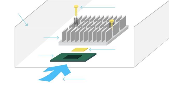
Once the thermal resistance target has been calculated, a heat sink can then be selected, based on the following 6 design factors below:
| 1. Heat Source 2. Heat Sink 3. Air Duct 4. Air Flow 5. Thermal Interface 6. Attachment |
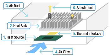
Click on each design factor and input as much information as possible. It is not necessary to input all of the requested information, if you are not sure. For any omitted information, we will use a typical value.
Heat sink performance depends on many factors, some of which may not covered in this section. We will provide the proposed solution based on our test data and experience. However, due to complex nature of the of the various factors, the final performance could not be guaranteed. Customers are responsible to verify performance in their actual operating environment.
Close
2.Sendwhen you are done
Please confirm your inputs and enter your contact information along with any additional relevant information. Once the request is sent, we will review and contact you by email.
Duct Size (H)
mm
mm
Duct Size (W)
mm
mm
Heat Sink (H)
mm
mm
Ambient
°C
°C
Heat Sink (W): mm
Heat Sink (L): mm
Heat Sink (L): mm
Max Case Temp: °C
Wattage: W
Wattage: W
Air Flow:
Air Speed: m/s
Air Speed: m/s
Thermal Resistance: °C/W
Input Data
1.
Heat Source :
2.
Heat Sink :
3.
Air Duct :
4.
Air Flow :
5.
Thermal Interface :
6.
Attachment :
Contact Information
* The fields with an asterisk(*) are required.
| Company Name * | Department/Division |
|---|---|
| Country * | Name * |
| Email * | Phone # |
Additional Info
1. Heat Source
2. Heat Sink
3. Air Duct
4. Air Flow
5. Thermal Interface
6. Attachment
1 .Heat Source/
2 .Heat Sink/
3 .Air Duct/
4 .Air Flow/
5 .Thermal Interface/
6 .Attachment/
1.Heat Source
Input IC Chip (Heat Source) Specification
Target thermal performance
Power consumption(TDP) (W)
Maximum allowed case temperature (°C)
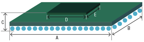
IC chip(heat source) size
| A (mm) | B (mm) | C (mm) | D (mm) | E (mm) |
|---|---|---|---|---|
Chip manufacturer and model number
Additional Info
Setting The Specifications For an IC/Chip in the Heat Sink Selection Process
In order to properly select/design a heat sink,we need to clearly specify the operating conditions and calculate a thermal resistance target for the heat sink.
Please answer the following questions in as much detail as possible.
If you cannot answer a question, leave it blank, and we will fill in a typical value based on our experience.
After answering the questions, please push the "Request" button.We will review your responses and provide feedback ASAP.
Please fill in items 1 through 6, answering the questions as completely as possible.
If you are unsure about a question, leave it blank.
After completing all sections, press the "Request" button above to submit your information.
Examples of published IC/Chip specifications:
Intel®G31/P31 Express Chipset Thermal and Mechanical Design Guidelines
The power dissipation and the maximum allowed case temperature are provided. The TDP(Thermal Design Power) is 15.5(W), and the Max. case temperature is 106 °C. The maximum allowed temperature increase is calculated by subtracting the Max. local ambient temperature from the Max. case or junction temperature The Max. local ambient temperature is the temperature of the air that will enter the heat sink cooling the the IC/chip. This value cannot be predetermined and will be your responsibility to specify. However, using 45-55 °C as the Max. local ambient is often used for electronics enclosures and telecommunications equipment, in our experience. If we assume 45 °C for the Max. local ambient temperature, then the maximum allowable temperature rise would be 106-45 = 61°C, in this example. The target thermal resistance can then be calculated by dividing the allowable temperature rise by the thermal design power of 15.5 Watts: (106-45)/15.5 = 3.94 °C/W
"Altera Device Packaging Specifications"
Here is an example of a package's mechanical specifications. D1 and E1 dimensions are critical in estimating the thermal performance of the heat sink and in the selection of the thermal interface material. D and E dimensions are critical in the mechanical design of the heat sink and the attachment hardware.
Close
2.Heat Sink
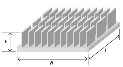
Input Heat Sink Size Requirements
Maximum allowed heat sink size (if any)
| W:Width(mm) | L:Length(mm) | H:Height(mm) |
|---|---|---|
If you only know the height limitation, simply enter this number.
Target thermal resistance (for the heat sink) (°C/W)
Additional Information
Regarding a heat sink size
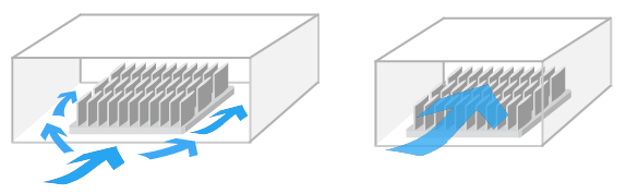
A larger heat sink will typically perform better, as the surface area of the heat sink will become greater. Also, by increasing the volume of the heat sink, the amount of bypass area around the heat sink will be reduced, forcing more airflow to go through the heat sink.
Bypass Air Flow (Large)
Bypass Air Flow (Small)
However, a larger heat sink may require a more complicated and expensive attachment method. Push pins or shoulder screws versus thermal tape or epoxy. (REF:Online Catalog - Heat Sink Attachment)
If mechanical attachment hardware like push pins or shoulder screws are used, holes in the PCB must be located outside of the chip’s footprint. This will require the use of a larger heat sink or a heat sink with attachment tabs.
Close
3.Air Duct
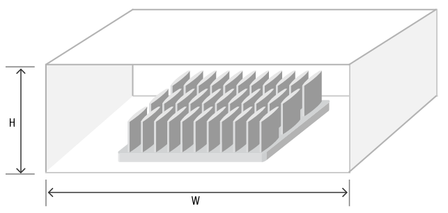
Input Duct Size
Duct Size
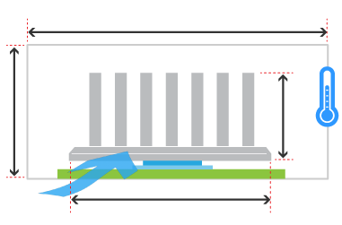
Has a formal duct been created to prevent air from bypassing around the heat sink? In the actual environment, if no duct has been created, other components like a daughter card, memory module, PCB components, the chassis, etc..., will act like a duct and help to channel the air. The estimated size of the duct created by these components is useful. If this detailed information is not available, just having height information for the chassis itself can be very useful.
| W:Width(mm) | H:Height(mm) |
|---|---|
Additional Info
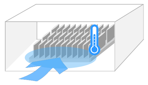
Bypass Considerations
If there is a lot of space around the heat sink, a significant amount of the air will flow around the heat sink instead of going through it. We call this bypass air flow.
Having a duct that channels the air, forcing it into the heat sink, will significantly improve the thermal performance.
Bypass Air Flow (Large)
Bypass Air Flow (Small)
The thermal resistance test data in our catalog is based on fully ducted air flow conditions. Therefore, the performance curve in our catalog is measured under ideal conditions. (Ref:Technical information - Measurement & Calculations).
In the actual environment, if no duct has been created, other components like a daughter card, memory module, PCB components, the chassis, etc..., will act like a duct and help to channel the air.
Depending on the duct size, the heat sink performance will vary. Generally, the performance of a heat sink with a denser fin pattern and higher pressure drop will be more sensitive to the duct size and the amount of bypass airflow.
Typically, the adjacent board or chassis wall will act as a duct, minimizing the amount of bypass space over the top of the heat sink. If no information is entered for the duct size height, we will assume that the duct size is equal to the heat sink size plus 2mm.
Close
4.Air Flow
Input Air Flow Conditions
Ambient Temperature (°C)
Target Thermal Performance
Heat sink position
Air speed(m/s)
Additional Info
Aiflow Condition
The air flow condition can be classified as Natural Convection or Forced convection.
Natural convection is a condition where the air flow is only generated by a a temperature differential and NOT by external means like a fan or blower.
Forced Convection is a condition where air flow IS generated by an external source like a fan or blower.
Greater air speed will result in better thermal performance.
In the actual environment, the air speed generated by a fan or blower will depend on many factors, such as where the components are located relative to the heat sinks, and fin pattern density of the heat sinks that are used.
The air speed used for simulation is ithe inlet air speed, just in front of the heat sink.
5.Thermal Interface
Input Thermal Interface Material (TIM) Preference
The following is a list of typical Alpha Standard TIM products. We carry many additional TIM products.
If you have requests, please input this information in the memo (Additional Information) section.
Additional Info
Interface Material
Thermal interface material(TIM) fills the small gaps and imperfections between the heat sink and heat source, minimizing the interface thermal resistance.
Please visit Online Catalog - Accessory - Thermal Interface Material.
If you choose adhesive tape for heat sink attachment, the adhesive tape itself is also the thermal interface material.
Pleaes visit Online Catalog - Accessory - Thermally conductive Adhesive Tape.
Generally, as the heat source size becomes smaller, the performance characteristics of the TIM becomes far more significant.
6.Attachment
Select Attachment Method
Additional Info
Heat Sink Attachment
The heat sink attachment method is one of the most important factors regarding heat sink design. The method of heat sink attachment will have an impact on the selection of thermal interface material. For more details, please visit Online Catalog - Heat Sink Attachment.
Thank you for your request.
If you do not hear from us within 2 business days, please contact our sales department.
Request ID:
Input Data
1.
Heat Source :
(Unknown)
2.
Heat Sink :
(Unknown)
3.
Air Duct :
(Unknown)
4.
Air Flow :
(Unknown)
5.
Thermal Interface :
(Unknown)
6.
Attachment :
(Unknown)
Contact Information
| Company Name * | Department/Division |
|---|---|
| Country * | Name * |
| Email * | Tel |
| Additional Info | |
Input check
Input check
Input check