
Technical Information
Measurement & Calculations
Measurement Apparatus and Method
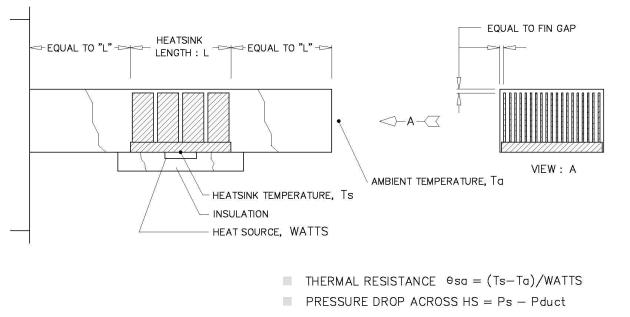
The thermal performance for forced convection are measured as shown Figure 1, 2.
Figure 1: The Overall Experimental Setup
Figure 2: Duct Dimensions, Experimental Setup
- Airflow test chamber .The chamber, manufactured by Airflow Measurement Systems, is designed in accordance with AMCA 210-85 standards.
- Please see each test condition for Heater Size
- A 1.4mm hole at the center of the test heat sink is made, and a thermocouple is inserted to the heater. A small amount of thermal grease is applied evenly between heater and heat sink base. Typically, data measurements are taken multiple times.
Reference:
- Patel, C., Belady C., "Modeling and Metrology in High Performance Heat Sink Design", Porceedings of the 47th Electronic Components and Technology Conference, IEEE, P.296, San Jose, California, 1997.
- AMCA 210-85
The thermal performance for active heat sink are measured as shown Figure 3,4.
- Please see each test condition for Heater Size
- A 1.4mm hole at the center of the test heat sink is made, and a thermocouple is inserted to the heater. A small amount of thermal grease is applied evenly between heater and heat sink base. Typically, data measurements are taken multiple times.
The thermal performance for natural convection are measured as shown Figure 5.
- Please see each test condition for Heater Size
- A 1.4mm hole at the center of the test heat sink is made, and a thermocouple is inserted to the heater. A small amount of thermal grease is applied evenly between heater and heat sink base. Typically, data measurements are taken multiple times.
© 2007-2022 Alpha Novatech, Inc.