
Technical Information
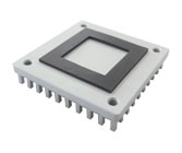
Guideline for small size heat source(bare-chip)
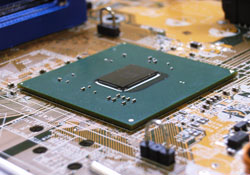
There are several issues to consider when attaching a heat sink to a heat source with a small contact area or bare die.
- Possibility of heat sink tipping/tilting.
- Possibility of the exposed die being damaged during heat sink installation.
- Contact area can be too small to form a strong bond with epoxy or tape attachment.
Typical attachment method and its suitablity for small heat source is as follows.
| Attachment method | Suitability | Memo | |
|---|---|---|---|
|
Thermally conductive epoxy | Not suitable | Due to the small contact area, the epoxy will not provide sufficient bond strength. Also, the relatively high impedance of epoxy will affect the thermal performance significnatly. |
 |
Thermally conductive adhsive tape | Not suitable | Due to the small contact area, the tape will not provide sufficient bond strength. Also, the relatively high impedance of tape will affect the thermal performance significnatly. |
 |
Plastic clip | Not suitable | Solder balls or chip substrate may be damaged during heat sink assembly due to
localized stress. Also, the heat sink size is limited to the chip/clip size. |
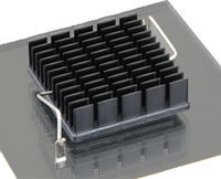 |
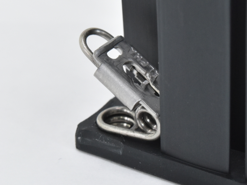
Z-Clip | Good | Provides stable attachment to heat source and transfers load to mounting anchors/PCB. |
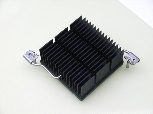 |
QSZ-Clip | Good | Provides stable attachment to heat source and transfers load to mounting anchors/PCB. |
 |
QuickSet | Good | The anchor pins are located inside of the heat sink footprint, they will act as guides when t he heat sink is installed. The tight clearance between the anchor pins and the clearance holes will greatly reduce the ability of the heat sink to tip or tilt during installation, preventing contact with the edges or corners of the die. |
 |
Push-Pin | Good | Provides stable attachment to heat source and transfers load to PCB. Also, allows for tight control over mounting force and load placed on chip and solder balls. |
 |
Shoulder Screws | Excellent | Provides stable attachment to heat source and transfers load to PCB, backing
plate or chassis. Suitable for high mass heat sinks. Also, allows for tight control over mounting force and load placed on chip and solder balls. |
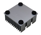
When a heat sink is attached to a small heat source, the heat sink can tip or tilt. If this happens, there is a possibility of damaging the die. To prevent this, we can apply sponge pads to the heat sink. The sponge pads help to stabilize the heat sink during attachment. We have several pad options, please click here for details.
Thermal Interface Material(TIM)is applied between the heat source and heat sink. When the heat source is small, the performance of TIM becomes far more significant. The following example illustrates the importance of TIM performance.
| Product | Size | Input Power | Thermal resistance | Temperature Rise |
|---|---|---|---|---|
| TPCM5125 | 35x35mm | 10W | 0.02degC/W | 0.20degC |
| 10x10mm | 0.20degC/W | 2.00degC | ||
| TPCM7125 | 35x35mm | 0.01degC/W | 0.10degC | |
| 10x10mm | 0.10degC/W | 1.00degC | ||
| TPCM585 | 35x35mm | 0.03degC/W | 0.30degC | |
| 10x10mm | 0.40degC/W | 4.00degC | ||
| TPCM905C | 35x35mm | 0.03degC/W | 0.30degC | |
| 10x10mm | 0.32degC/W | 3.20degC |
* at 69Kpa(10psi)
As this shows, the use of a high performance TIM has a very significnat impact when the heat source is
small.
Also, phase change material or gap filler
material requires a certain attachment pressure/load in order to perform properly. The following
examples display the impact of mounting pressure on phase change material performance.
| Product | Load | Thermal impedance |
|---|---|---|
| TPCM5125 | 69Kpa(10psi) | 0.20°C-cm2/W |
| 345Kpa(50psi) | 0.10°C-cm2/W | |
| TPCM7125 | 69Kpa(10psi) | 0.10°C-cm2/W |
| 345Kpa(50psi) | 0.06°C-cm2/W | |
| TPCM585 | 69Kpa(10psi) | 0.40°C-cm2/W |
| 345Kpa(50psi) | 0.15°C-cm2/W | |
| TPCM905C | 69Kpa(10psi) | 0.31 °C-cm2/W |
| 345Kpa(50psi) | 0.19 °C-cm2/W |
The use of a Z-Clip, Push Pin or Shoulder Screw for attachment allows tight control over the attachment pressure/load, ensuring acceptable performance from the TIM.
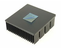
It is far more difficult to cool a smaller sized heat source. This is due the spreading resistnace of the heat sink's base material. The heat must first travel through the base in order to get to the outer fins.
Alpha's copper embedded heat sink makes it possible to spread the heat from a small heat source to the entire base far more easily. The copper embedded heat sink is efficient and reliable. (Standard copper embedded heat sink)