
Technical Information
Cooling multiple heat sources with a single heat sink
Cooling multiple heat sources with a single heat sink
Cooling multiple heat sources with a single heat sink is an attractive option,
but it can create critical design issues, and it may not be recommended.
However, there are cases where this design approach is advantageous,
so the following design considerations should be taken into account.
The most significant design consideration when cooling multiple heat sources
with a single heat sink is dealing with the stack up heights and tolerances of
the different devices.
For example, assume the cooling of two identical devices with one heat sink:
If the height tolerance is 0.1mm, the worst case height difference would be 0.2mm.
The heat sink may contact one chip, but not the other.
Or, the heat sink may contact both chips, but in a tilted orientation.
In either case, poor contact would be the result, creating a serious thermal issue.
There are two approaches to solving this issue.
The first approach is to use a thick and compliant gap pad as the thermal interface material.
This material will fill any gaps and ensure that contact is made between the heat sink and all devices.
However, gap pads offer inferior thermal performance compared to grease or phase change material.
If one of the heat sources is a critical component dissipating high thermal loads,
this approach can severely impact the performance and reliability of the device.
The second approach is to use grease or a phase change material (PCM) on the most important
device and gap pad material on the other devices.
Through the use of pedestals, we can ensure initial contact with the device dissipating
the high heat load and use a high performance interface material like grease or phase change material.
Thicker gap pad material can be used for the heat sources with lower heat loads.
This approach may require a gap pad material with even larger deformation properties than the first
approach.
An advantage of this approach is that the high load device now has a much larger heat sink
and surface area from which to dissipate its heat, improving its performance.
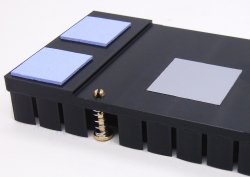
In either case, a relatively high attachment force is required to ensure that the gap pad material
is sufficiently compressed to allow the heat sink to make contact with each device.
All of our standard mounting options can be used in cooling multiple heat sources with a single heat sink.
This includes push pin/springs, clips, and shoulder screws.
The final approach would be based on a customer's preference.
The required attachment force may be higher than the allowable load for the device,
or depending on the tolerances, the heat sink may only contact the devices in a tilted orientation.
In these cases, we would not recommend the use of the single heat sink approach.
Unless there is enough thermal performance margin, we would not recommend
the use of the single heat sink due to the design issues mentioned above.
However, if a customer is willing to deal with these issues,
we can create a single heat sink for multiple devices.
However, our MicroForging process currently has a footprint area limitation of
approximately 10,000 to 12,000 square millimeters.
This would limit us to the use of a heat sink size of approximately 100x100mm.
| Pros |
|
|---|---|
| Cons |
|